編輯:關於Android編程
一、stitching_detail程序運行流程
1.命令行調用程序,輸入源圖像以及程序的參數
2.特征點檢測,判斷是使用surf還是orb,默認是surf。
3.對圖像的特征點進行匹配,使用最近鄰和次近鄰方法,將兩個最優的匹配的置信度保存下來。
4.對圖像進行排序以及將置信度高的圖像保存到同一個集合中,刪除置信度比較低的圖像間的匹配,得到能正確匹配的圖像序列。這樣將置信度高於門限的所有匹配合並到一個集合中。
5.對所有圖像進行相機參數粗略估計,然後求出旋轉矩陣
6.使用光束平均法進一步精准的估計出旋轉矩陣。
7.波形校正,水平或者垂直
8.拼接
9.融合,多頻段融合,光照補償,後續再改。
二、stitching_detail程序接口介紹
img1 img2 img3 輸入圖像
--preview 以預覽模式運行程序,比正常模式要快,但輸出圖像分辨率低,拼接的分辨率compose_megapix設置為0.6
--try_gpu (yes|no) 是否使用GPU(圖形處理器),默認為no
/* 運動估計參數 */
--work_megapix <--work_megapix > 圖像匹配的分辨率大小,圖像的面積尺寸變為work_megapix*100000,默認為0.6
--features (surf|orb) 選擇surf或者orb算法進行特征點計算,默認為surf
--match_conf 特征點檢測置信等級,最近鄰匹配距離與次近鄰匹配距離的比值,surf默認為0.65,orb默認為0.3
--conf_thresh 兩幅圖來自同一全景圖的置信度,默認為1.0
--ba (reproj|ray) 光束平均法的誤差函數選擇,默認是ray方法
--ba_refine_mask (mask) ---------------
--wave_correct (no|horiz|vert) 波形校驗 水平,垂直或者沒有 默認是horiz
--save_graph 將匹配的圖形以點的形式保存到文件中, Nm代表匹配的數量,NI代表正確匹配的數量,C表示置信度
/*圖像融合參數:*/
--warp (plane|cylindrical|spherical|fisheye|stereographic|compressedPlaneA2B1|compressedPlaneA1.5B1|compressedPlanePortraitA2B1
|compressedPlanePortraitA1.5B1|paniniA2B1|paniniA1.5B1|paniniPortraitA2B1|paniniPortraitA1.5B1|mercator|transverseMercator)
選擇融合的平面,默認是球形
--seam_megapix 拼接縫像素的大小 默認是0.1 ------------
--seam (no|voronoi|gc_color|gc_colorgrad) 拼接縫隙估計方法 默認是gc_color
--compose_megapix 拼接分辨率,默認為-1
--expos_comp (no|gain|gain_blocks) 光照補償方法,默認是gain_blocks
--blend (no|feather|multiband) 融合方法,默認是多頻段融合
--blend_strength 融合強度,0-100.默認是5.
--output 輸出圖像的文件名,默認是result,jpg
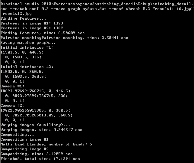
命令使用實例,以及程序運行時的提示:
三、程序代碼分析
1.參數讀入
程序參數讀入分析,將程序運行是輸入的參數以及需要拼接的圖像讀入內存,檢查圖像是否多於2張。
int retval = parseCmdArgs(argc, argv);
if (retval)
return retval;
// Check if have enough images
int num_images = static_cast(img_names.size());
if (num_images < 2)
{
LOGLN("Need more images");
return -1;
}
2.特征點檢測
判斷選擇是surf還是orb特征點檢測(默認是surf)以及對圖像進行預處理(尺寸縮放),然後計算每幅圖形的特征點,以及特征點描述子
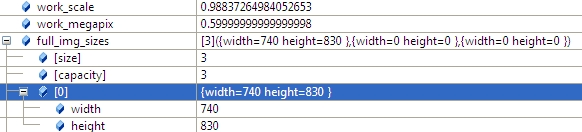
2.1 計算work_scale,將圖像resize到面積在work_megapix*10^6以下,(work_megapix 默認是0.6)
work_scale = min(1.0, sqrt(work_megapix * 1e6 / full_img.size().area()));
resize(full_img, img, Size(), work_scale, work_scale);
圖像大小是740*830,面積大於6*10^5,所以計算出work_scale = 0.98,然後對圖像resize。
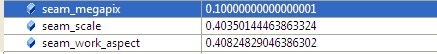
2.2 計算seam_scale,也是根據圖像的面積小於seam_megapix*10^6,(seam_megapix 默認是0.1),seam_work_aspect目前還沒用到
seam_scale = min(1.0, sqrt(seam_megapix * 1e6 / full_img.size().area()));
seam_work_aspect = seam_scale / work_scale; //seam_megapix = 0.1 seam_work_aspect = 0.69
2.3 計算圖像特征點,以及計算特征點描述子,並將img_idx設置為i。
(*finder)(img, features[i]);//matcher.cpp 348
features[i].img_idx = i;
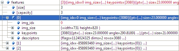
特征點描述的結構體定義如下:
struct detail::ImageFeatures
Structure containing image keypoints and descriptors.
struct CV_EXPORTS ImageFeatures
{
int img_idx;//
Size img_size;
std::vector keypoints;
Mat descriptors;
};
2.4 將源圖像resize到seam_megapix*10^6,並存入image[]中
resize(full_img, img, Size(), seam_scale, seam_scale);
images[i] = img.clone();
3.圖像匹配
對任意兩副圖形進行特征點匹配,然後使用查並集法,將圖片的匹配關系找出,並刪除那些不屬於同一全景圖的圖片。
3.1 使用最近鄰和次近鄰匹配,對任意兩幅圖進行特征點匹配。
vector pairwise_matches;//Structure containing information about matches between two images.
BestOf2NearestMatcher matcher(try_gpu, match_conf);//最近鄰和次近鄰法
matcher(features, pairwise_matches);//對每兩個圖片進行matcher,20-》400 matchers.cpp 502
介紹一下BestOf2NearestMatcher 函數:
//Features matcher which finds two best matches for each feature and leaves the best one only if the ratio between descriptor distances is greater than the threshold match_conf.
detail::BestOf2NearestMatcher::BestOf2NearestMatcher(bool try_use_gpu=false,float match_conf=0.3f,
intnum_matches_thresh1=6, int num_matches_thresh2=6)
Parameters: try_use_gpu – Should try to use GPU or not
match_conf – Match distances ration threshold
num_matches_thresh1 – Minimum number of matches required for the 2D projective
transform estimation used in the inliers classification step
num_matches_thresh2 – Minimum number of matches required for the 2D projective
transform re-estimation on inliers
函數的定義(只是設置一下參數,屬於構造函數):
BestOf2NearestMatcher::BestOf2NearestMatcher(bool try_use_gpu, float match_conf, int num_matches_thresh1, int num_matches_thresh2)
{
#ifdef HAVE_OPENCV_GPU
if (try_use_gpu && getCudaEnabledDeviceCount() > 0)
impl_ = new GpuMatcher(match_conf);
else
#else
(void)try_use_gpu;
#endif
impl_ = new CpuMatcher(match_conf);
is_thread_safe_ = impl_->isThreadSafe();
num_matches_thresh1_ = num_matches_thresh1;
num_matches_thresh2_ = num_matches_thresh2;
}
以及MatchesInfo的結構體定義:
Structure containing information about matches between two images. It’s assumed that there is a homography between those images.
struct CV_EXPORTS MatchesInfo
{
MatchesInfo();
MatchesInfo(const MatchesInfo &other);
const MatchesInfo& operator =(const MatchesInfo &other);
int src_img_idx, dst_img_idx; // Images indices (optional)
std::vector matches;
std::vector inliers_mask; // Geometrically consistent matches mask
int num_inliers; // Number of geometrically consistent matches
Mat H; // Estimated homography
double confidence; // Confidence two images are from the same panorama
};
求出圖像匹配的結果如下(具體匹配參見sift特征點匹配),任意兩幅圖都進行匹配(3*3=9),其中1-》2和2-》1只計算了一次,以1-》2為准,:
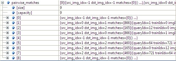
3.2 根據任意兩幅圖匹配的置信度,將所有置信度高於conf_thresh(默認是1.0)的圖像合並到一個全集中。
我們通過函數的參數 save_graph打印匹配結果如下(我稍微修改了一下輸出):
"outimage101.jpg" -- "outimage102.jpg"[label="Nm=866, Ni=637, C=2.37864"];
"outimage101.jpg" -- "outimage103.jpg"[label="Nm=165, Ni=59, C=1.02609"];
"outimage102.jpg" -- "outimage103.jpg"[label="Nm=460, Ni=260, C=1.78082"];
Nm代表匹配的數量,NI代表正確匹配的數量,C表示置信度
vector indices = leaveBiggestComponent(features, pairwise_matches, conf_thresh);//將置信度高於門限的所有匹配合並到一個集合中
vector img_subset;
vector img_names_subset;
vector full_img_sizes_subset;
for (size_t i = 0; i < indices.size(); ++i)
{
img_names_subset.push_back(img_names[indices[i]]);
img_subset.push_back(images[indices[i]]);
full_img_sizes_subset.push_back(full_img_sizes[indices[i]]);
}
images = img_subset;
img_names = img_names_subset;
full_img_sizes = full_img_sizes_subset;
4.根據單應性矩陣粗略估計出相機參數(焦距)
4.1 焦距參數的估計
根據前面求出的任意兩幅圖的匹配,我們根據兩幅圖的單應性矩陣H,求出符合條件的f,(4副圖,16個匹配,求出8個符合條件的f),然後求出f的均值或者中值當成所有圖形的粗略估計的f。
view plain copy print?
estimateFocal(features,pairwise_matches,focals);
estimateFocal(features, pairwise_matches, focals);
函數的主要源碼如下:
view plain copy print?
for(inti=0;ifor(intj=0;jconstMatchesInfo&m=pairwise_matches[i*num_images+j];if(m.H.empty())
continue;doublef0,f1;
boolf0ok,f1ok;focalsFromHomography(m.H,f0,f1,f0ok,f1ok);//Triestoestimatefocallengthsfromthegivenhomography79
//undertheassumptionthatthecameraundergoesrotationsarounditscentreonly.if(f0ok&&f1ok)
all_focals.push_back(sqrt(f0*f1));}
}
for (int i = 0; i < num_images; ++i)
{
for (int j = 0; j < num_images; ++j)
{
const MatchesInfo &m = pairwise_matches[i*num_images + j];
if (m.H.empty())
continue;
double f0, f1;
bool f0ok, f1ok;
focalsFromHomography(m.H, f0, f1, f0ok, f1ok);//Tries to estimate focal lengths from the given homography 79
//under the assumption that the camera undergoes rotations around its centre only.
if (f0ok && f1ok)
all_focals.push_back(sqrt(f0 * f1));
}
}
其中函數focalsFromHomography的定義如下:
view plain copy print?
Triestoestimatefocallengthsfromthegivenhomographyundertheassumptionthatthecameraundergoesrotationsarounditscentreonly.
ParametersH–Homography.
f0–EstimatedfocallengthalongXaxis.f1–EstimatedfocallengthalongYaxis.
f0_ok–True,iff0wasestimatedsuccessfully,falseotherwise.f1_ok–True,iff1wasestimatedsuccessfully,falseotherwise.
Tries to estimate focal lengths from the given homography
under the assumption that the camera undergoes rotations around its centre only.
Parameters
H – Homography.
f0 – Estimated focal length along X axis.
f1 – Estimated focal length along Y axis.
f0_ok – True, if f0 was estimated successfully, false otherwise.
f1_ok – True, if f1 was estimated successfully, false otherwise.
函數的源碼:
view plain copy print?
voidfocalsFromHomography(constMat&H,double&f0,double&f1,bool&f0_ok,bool&f1_ok){
CV_Assert(H.type()==CV_64F&&H.size()==Size(3,3));//Checksaconditionatruntimeandthrowsexceptionifitfails
constdouble*h=reinterpret_cast(H.data);//強制類型轉換
doubled1,d2;//Denominatorsdoublev1,v2;//Focalsquaresvaluecandidates
//具體的計算過程有點看不懂啊
f1_ok=true;d1=h[6]*h[7];
d2=(h[7]-h[6])*(h[7]+h[6]);v1=-(h[0]*h[1]+h[3]*h[4])/d1;
v2=(h[0]*h[0]+h[3]*h[3]-h[1]*h[1]-h[4]*h[4])/d2;if(v1if(v1>0&&v2>0)f1=sqrt(std::abs(d1)>std::abs(d2)?v1:v2);elseif(v1>0)f1=sqrt(v1);
elsef1_ok=false;
f0_ok=true;d1=h[0]*h[3]+h[1]*h[4];
d2=h[0]*h[0]+h[1]*h[1]-h[3]*h[3]-h[4]*h[4];v1=-h[2]*h[5]/d1;
v2=(h[5]*h[5]-h[2]*h[2])/d2;if(v1if(v1>0&&v2>0)f0=sqrt(std::abs(d1)>std::abs(d2)?v1:v2);elseif(v1>0)f0=sqrt(v1);
elsef0_ok=false;}
void focalsFromHomography(const Mat& H, double &f0, double &f1, bool &f0_ok, bool &f1_ok)
{
CV_Assert(H.type() == CV_64F && H.size() == Size(3, 3));//Checks a condition at runtime and throws exception if it fails
const double* h = reinterpret_cast(H.data);//強制類型轉換
double d1, d2; // Denominators
double v1, v2; // Focal squares value candidates
//具體的計算過程有點看不懂啊
f1_ok = true;
d1 = h[6] * h[7];
d2 = (h[7] - h[6]) * (h[7] + h[6]);
v1 = -(h[0] * h[1] + h[3] * h[4]) / d1;
v2 = (h[0] * h[0] + h[3] * h[3] - h[1] * h[1] - h[4] * h[4]) / d2;
if (v1 < v2) std::swap(v1, v2);
if (v1 > 0 && v2 > 0) f1 = sqrt(std::abs(d1) > std::abs(d2) ? v1 : v2);
else if (v1 > 0) f1 = sqrt(v1);
else f1_ok = false;
f0_ok = true;
d1 = h[0] * h[3] + h[1] * h[4];
d2 = h[0] * h[0] + h[1] * h[1] - h[3] * h[3] - h[4] * h[4];
v1 = -h[2] * h[5] / d1;
v2 = (h[5] * h[5] - h[2] * h[2]) / d2;
if (v1 < v2) std::swap(v1, v2);
if (v1 > 0 && v2 > 0) f0 = sqrt(std::abs(d1) > std::abs(d2) ? v1 : v2);
else if (v1 > 0) f0 = sqrt(v1);
else f0_ok = false;
}
求出的焦距有8個
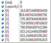
求出的焦距取中值或者平均值,然後就是所有圖片的焦距。
並構建camera參數,將矩陣寫入camera:
view plain copy print?
cameras.assign(num_images,CameraParams());for(inti=0;icameras[i].focal=focals[i];
cameras.assign(num_images, CameraParams());
for (int i = 0; i < num_images; ++i)
cameras[i].focal = focals[i];
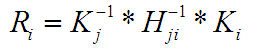
4.2 根據匹配的內點構建最大生成樹,然後廣度優先搜索求出根節點,並求出camera的R矩陣,K矩陣以及光軸中心
camera其他參數:
aspect = 1.0,ppx,ppy目前等於0,最後會賦值成圖像中心點的。
K矩陣的值:
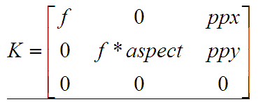
view plain copy print?
MatCameraParams::K()const{
Mat_k=Mat::eye(3,3,CV_64F);k(0,0)=focal;k(0,2)=ppx;
k(1,1)=focal*aspect;k(1,2)=ppy;returnk;
}
Mat CameraParams::K() const
{
Mat_ k = Mat::eye(3, 3, CV_64F);
k(0,0) = focal; k(0,2) = ppx;
k(1,1) = focal * aspect; k(1,2) = ppy;
return k;
}
R矩陣的值:
view plain copy print?
voidoperator()(constGraphEdge&edge){
intpair_idx=edge.from*num_images+edge.to;
Mat_K_from=Mat::eye(3,3,CV_64F);K_from(0,0)=cameras[edge.from].focal;
K_from(1,1)=cameras[edge.from].focal*cameras[edge.from].aspect;K_from(0,2)=cameras[edge.from].ppx;
K_from(0,2)=cameras[edge.from].ppy;
Mat_K_to=Mat::eye(3,3,CV_64F);K_to(0,0)=cameras[edge.to].focal;
K_to(1,1)=cameras[edge.to].focal*cameras[edge.to].aspect;K_to(0,2)=cameras[edge.to].ppx;
K_to(0,2)=cameras[edge.to].ppy;
MatR=K_from.inv()*pairwise_matches[pair_idx].H.inv()*K_to;cameras[edge.to].R=cameras[edge.from].R*R;
}
void operator ()(const GraphEdge &edge)
{
int pair_idx = edge.from * num_images + edge.to;
Mat_ K_from = Mat::eye(3, 3, CV_64F);
K_from(0,0) = cameras[edge.from].focal;
K_from(1,1) = cameras[edge.from].focal * cameras[edge.from].aspect;
K_from(0,2) = cameras[edge.from].ppx;
K_from(0,2) = cameras[edge.from].ppy;
Mat_ K_to = Mat::eye(3, 3, CV_64F);
K_to(0,0) = cameras[edge.to].focal;
K_to(1,1) = cameras[edge.to].focal * cameras[edge.to].aspect;
K_to(0,2) = cameras[edge.to].ppx;
K_to(0,2) = cameras[edge.to].ppy;
Mat R = K_from.inv() * pairwise_matches[pair_idx].H.inv() * K_to;
cameras[edge.to].R = cameras[edge.from].R * R;
}
光軸中心的值
view plaincopyprint?
for(inti=0;icameras[i].ppx+=0.5*features[i].img_size.width;cameras[i].ppy+=0.5*features[i].img_size.height;
}

for (int i = 0; i < num_images; ++i)
{
cameras[i].ppx += 0.5 * features[i].img_size.width;
cameras[i].ppy += 0.5 * features[i].img_size.height;
}
5.使用Bundle Adjustment方法對所有圖片進行相機參數校正
Bundle Adjustment(光束法平差)算法主要是解決所有相機參數的聯合。這是全景拼接必須的一步,因為多個成對的單應性矩陣合成全景圖時,會忽略全局的限制,造成累積誤差。因此每一個圖像都要加上光束法平差值,使圖像被初始化成相同的旋轉和焦距長度。
光束法平差的目標函數是一個具有魯棒性的映射誤差的平方和函數。即每一個特征點都要映射到其他的圖像中,計算出使誤差的平方和最小的相機參數。具體的推導過程可以參見Automatic Panoramic Image Stitching using Invariant Features.pdf的第五章,本文只介紹一下opencv實現的過程(完整的理論和公式 暫時還沒看懂,希望有人能一起交流)
opencv中誤差描述函數有兩種如下:(opencv默認是BundleAdjusterRay):
view plaincopyprint?
BundleAdjusterReproj//BundleAdjusterBase(7,2)//最小投影誤差平方和Implementationofthecameraparametersrefinementalgorithmwhichminimizessumofthereprojectionerrorsquares
BundleAdjusterRay//BundleAdjusterBase(4,3)//最小特征點與相機中心點的距離和
Implementationofthecameraparametersrefinementalgorithmwhichminimizessumofthedistancesbetweentherayspassingthroughthecameracenterandafeature.
BundleAdjusterReproj // BundleAdjusterBase(7, 2)//最小投影誤差平方和
Implementation of the camera parameters refinement algorithm which minimizes sum of the reprojection error squares
BundleAdjusterRay // BundleAdjusterBase(4, 3)//最小特征點與相機中心點的距離和
Implementation of the camera parameters refinement algorithm which minimizes sum of the distances between the
rays passing through the camera center and a feature.
5.1 首先計算cam_params_的值:
view plaincopyprint?
setUpInitialCameraParams(cameras);
setUpInitialCameraParams(cameras);
函數主要源碼:
view plaincopyprint?
cam_params_.create(num_images_*4,1,CV_64F);SVDsvd;//奇異值分解
for(inti=0;icam_params_.at(i*4,0)=cameras[i].focal;
svd(cameras[i].R,SVD::FULL_UV);MatR=svd.u*svd.vt;
if(determinant(R)<0)R*=-1;
Matrvec;
Rodrigues(R,rvec);CV_Assert(rvec.type()==CV_32F);
cam_params_.at(i*4+1,0)=rvec.at(0,0);cam_params_.at(i*4+2,0)=rvec.at(1,0);
cam_params_.at(i*4+3,0)=rvec.at(2,0);}
cam_params_.create(num_images_ * 4, 1, CV_64F);
SVD svd;//奇異值分解
for (int i = 0; i < num_images_; ++i)
{
cam_params_.at(i * 4, 0) = cameras[i].focal;
svd(cameras[i].R, SVD::FULL_UV);
Mat R = svd.u * svd.vt;
if (determinant(R) < 0)
R *= -1;
Mat rvec;
Rodrigues(R, rvec);
CV_Assert(rvec.type() == CV_32F);
cam_params_.at(i * 4 + 1, 0) = rvec.at(0, 0);
cam_params_.at(i * 4 + 2, 0) = rvec.at(1, 0);
cam_params_.at(i * 4 + 3, 0) = rvec.at(2, 0);
}
計算cam_params_的值,先初始化cam_params(num_images_*4,1,CV_64F);
cam_params_[i*4+0] = cameras[i].focal;
cam_params_後面3個值,是cameras[i].R先經過奇異值分解,然後對u*vt進行Rodrigues運算,得到的rvec第一行3個值賦給cam_params_。
奇異值分解的定義:
在矩陣M的奇異值分解中 M = UΣV* ·U的列(columns)組成一套對M的正交"輸入"或"分析"的基向量。這些向量是MM*的特征向量。 ·V的列(columns)組成一套對M的正交"輸出"的基向量。這些向量是M*M的特征向量。 ·Σ對角線上的元素是奇異值,可視為是在輸入與輸出間進行的標量的"膨脹控制"。這些是M*M及MM*的奇異值,並與U和V的行向量相對應。
5.2 刪除置信度小於門限的匹配對
view plaincopyprint?
//Leaveonlyconsistentimagepairsedges_.clear();
for(inti=0;ifor(intj=i+1;jconstMatchesInfo&matches_info=pairwise_matches_[i*num_images_+j];if(matches_info.confidence>conf_thresh_)
edges_.push_back(make_pair(i,j));}
}
// Leave only consistent image pairs
edges_.clear();
for (int i = 0; i < num_images_ - 1; ++i)
{
for (int j = i + 1; j < num_images_; ++j)
{
const MatchesInfo& matches_info = pairwise_matches_[i * num_images_ + j];
if (matches_info.confidence > conf_thresh_)
edges_.push_back(make_pair(i, j));
}
}
5.3 使用LM算法計算camera參數。
首先初始化LM的參數(具體理論還沒有看懂)
view plaincopyprint?
//計算所有內點之和for(size_ti=0;itotal_num_matches_+=static_cast(pairwise_matches[edges_[i].first*num_images_+edges_[i].second].num_inliers);
CvLevMarqsolver(num_images_*num_params_per_cam_,
total_num_matches_*num_errs_per_measurement_,term_criteria_);
Materr,jac;
CvMatmatParams=cam_params_;cvCopy(&matParams,solver.param);
intiter=0;
for(;;)//類似於while(1),但是比while(1)效率高{
constCvMat*_param=0;CvMat*_jac=0;
CvMat*_err=0;
boolproceed=solver.update(_param,_jac,_err);
cvCopy(_param,&matParams);
if(!proceed||!_err)break;
if(_jac)
{calcJacobian(jac);//構造雅閣比行列式
CvMattmp=jac;cvCopy(&tmp,_jac);
}
if(_err){
calcError(err);//計算errLOG_CHAT(".");
iter++;CvMattmp=err;
cvCopy(&tmp,_err);}
}
//計算所有內點之和
for (size_t i = 0; i < edges_.size(); ++i)
total_num_matches_ += static_cast(pairwise_matches[edges_[i].first * num_images_ +
edges_[i].second].num_inliers);
CvLevMarq solver(num_images_ * num_params_per_cam_,
total_num_matches_ * num_errs_per_measurement_,
term_criteria_);
Mat err, jac;
CvMat matParams = cam_params_;
cvCopy(&matParams, solver.param);
int iter = 0;
for(;;)//類似於while(1),但是比while(1)效率高
{
const CvMat* _param = 0;
CvMat* _jac = 0;
CvMat* _err = 0;
bool proceed = solver.update(_param, _jac, _err);
cvCopy(_param, &matParams);
if (!proceed || !_err)
break;
if (_jac)
{
calcJacobian(jac); //構造雅閣比行列式
CvMat tmp = jac;
cvCopy(&tmp, _jac);
}
if (_err)
{
calcError(err);//計算err
LOG_CHAT(".");
iter++;
CvMat tmp = err;
cvCopy(&tmp, _err);
}
}
計算camera
view plaincopyprint?
obtainRefinedCameraParams(cameras);//Getstherefinedcameraparameters.
obtainRefinedCameraParams(cameras);//Gets the refined camera parameters.
函數源代碼:
view plaincopyprint?
voidBundleAdjusterRay::obtainRefinedCameraParams(vector&cameras)const{
for(inti=0;icameras[i].focal=cam_params_.at(i*4,0);
Matrvec(3,1,CV_64F);rvec.at(0,0)=cam_params_.at(i*4+1,0);
rvec.at(1,0)=cam_params_.at(i*4+2,0);rvec.at(2,0)=cam_params_.at(i*4+3,0);
Rodrigues(rvec,cameras[i].R);
Mattmp;cameras[i].R.convertTo(tmp,CV_32F);
cameras[i].R=tmp;}
}
void BundleAdjusterRay::obtainRefinedCameraParams(vector &cameras) const
{
for (int i = 0; i < num_images_; ++i)
{
cameras[i].focal = cam_params_.at(i * 4, 0);
Mat rvec(3, 1, CV_64F);
rvec.at(0, 0) = cam_params_.at(i * 4 + 1, 0);
rvec.at(1, 0) = cam_params_.at(i * 4 + 2, 0);
rvec.at(2, 0) = cam_params_.at(i * 4 + 3, 0);
Rodrigues(rvec, cameras[i].R);
Mat tmp;
cameras[i].R.convertTo(tmp, CV_32F);
cameras[i].R = tmp;
}
}
求出根節點,然後歸一化旋轉矩陣R
view plaincopyprint?
//NormalizemotiontocenterimageGraphspan_tree;
vectorspan_tree_centers;findMaxSpanningTree(num_images_,pairwise_matches,span_tree,span_tree_centers);
MatR_inv=cameras[span_tree_centers[0]].R.inv();for(inti=0;icameras[i].R=R_inv*cameras[i].R;
// Normalize motion to center image
Graph span_tree;
vector span_tree_centers;
findMaxSpanningTree(num_images_, pairwise_matches, span_tree, span_tree_centers);
Mat R_inv = cameras[span_tree_centers[0]].R.inv();
for (int i = 0; i < num_images_; ++i)
cameras[i].R = R_inv * cameras[i].R;
6 波形校正
前面幾節把相機旋轉矩陣計算出來,但是還有一個因素需要考慮,就是由於拍攝者拍攝圖片的時候不一定是水平的,輕微的傾斜會導致全景圖像出現飛機曲線,因此我們要對圖像進行波形校正,主要是尋找每幅圖形的“上升向量”(up_vector),使他校正成
。
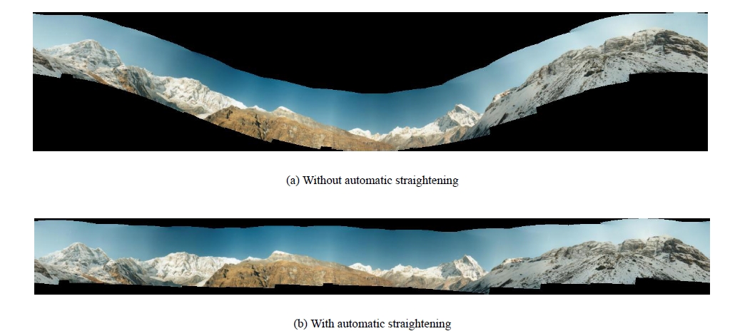
波形校正的效果圖
opencv實現的源碼如下(也是暫時沒看懂,囧)
view plaincopyprint?
vectorrmats;for(size_ti=0;irmats.push_back(cameras[i].R);waveCorrect(rmats,wave_correct);//Triestomakepanoramamorehorizontal(orvertical).
for(size_ti=0;i
vector rmats;
for (size_t i = 0; i < cameras.size(); ++i)
rmats.push_back(cameras[i].R);
waveCorrect(rmats, wave_correct);//Tries to make panorama more horizontal (or vertical).
for (size_t i = 0; i < cameras.size(); ++i)
cameras[i].R = rmats[i];
其中waveCorrect(rmats, wave_correct)源碼如下:
view plaincopyprint?
voidwaveCorrect(vector&rmats,WaveCorrectKindkind){
LOGLN("Wavecorrecting...");#ifENABLE_LOG
int64t=getTickCount();#endif
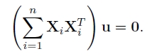
Matmoment=Mat::zeros(3,3,CV_32F);
for(size_ti=0;iMatcol=rmats[i].col(0);moment+=col*col.t();//相機R矩陣第一列轉置相乘然後相加
}Mateigen_vals,eigen_vecs;
eigen(moment,eigen_vals,eigen_vecs);//Calculateseigenvaluesandeigenvectorsofasymmetricmatrix.
Matrg1;if(kind==WAVE_CORRECT_HORIZ)
rg1=eigen_vecs.row(2).t();//如果是水平校正,去特征向量的第三行elseif(kind==WAVE_CORRECT_VERT)
rg1=eigen_vecs.row(0).t();//如果是垂直校正,特征向量第一行else
CV_Error(CV_StsBadArg,"unsupportedkindofwavecorrection");
Matimg_k=Mat::zeros(3,1,CV_32F);for(size_ti=0;iimg_k+=rmats[i].col(2);//R函數第3列相加Matrg0=rg1.cross(img_k);//rg1與img_k向量積
rg0/=norm(rg0);//歸一化?
Matrg2=rg0.cross(rg1);
doubleconf=0;if(kind==WAVE_CORRECT_HORIZ)
{for(size_ti=0;iconf+=rg0.dot(rmats[i].col(0));//Computesadot-productoftwovectors.數量積if(conf<0)
{rg0*=-1;
rg1*=-1;}
}elseif(kind==WAVE_CORRECT_VERT)
{for(size_ti=0;iconf-=rg1.dot(rmats[i].col(0));if(conf<0)
{rg0*=-1;
rg1*=-1;}
}
MatR=Mat::zeros(3,3,CV_32F);Mattmp=R.row(0);
Mat(rg0.t()).copyTo(tmp);tmp=R.row(1);
Mat(rg1.t()).copyTo(tmp);tmp=R.row(2);
Mat(rg2.t()).copyTo(tmp);
for(size_ti=0;iLOGLN("Wavecorrecting,time:"<<((getTickCount()-t)/getTickFrequency())<<"sec");
}
void waveCorrect(vector &rmats, WaveCorrectKind kind)
{
LOGLN("Wave correcting...");
#if ENABLE_LOG
int64 t = getTickCount();
#endif
Mat moment = Mat::zeros(3, 3, CV_32F);
for (size_t i = 0; i < rmats.size(); ++i)
{
Mat col = rmats[i].col(0);
moment += col * col.t();//相機R矩陣第一列轉置相乘然後相加
}
Mat eigen_vals, eigen_vecs;
eigen(moment, eigen_vals, eigen_vecs);//Calculates eigenvalues and eigenvectors of a symmetric matrix.
Mat rg1;
if (kind == WAVE_CORRECT_HORIZ)
rg1 = eigen_vecs.row(2).t();//如果是水平校正,去特征向量的第三行
else if (kind == WAVE_CORRECT_VERT)
rg1 = eigen_vecs.row(0).t();//如果是垂直校正,特征向量第一行
else
CV_Error(CV_StsBadArg, "unsupported kind of wave correction");
Mat img_k = Mat::zeros(3, 1, CV_32F);
for (size_t i = 0; i < rmats.size(); ++i)
img_k += rmats[i].col(2);//R函數第3列相加
Mat rg0 = rg1.cross(img_k);//rg1與img_k向量積
rg0 /= norm(rg0);//歸一化?
Mat rg2 = rg0.cross(rg1);
double conf = 0;
if (kind == WAVE_CORRECT_HORIZ)
{
for (size_t i = 0; i < rmats.size(); ++i)
conf += rg0.dot(rmats[i].col(0));//Computes a dot-product of two vectors.數量積
if (conf < 0)
{
rg0 *= -1;
rg1 *= -1;
}
}
else if (kind == WAVE_CORRECT_VERT)
{
for (size_t i = 0; i < rmats.size(); ++i)
conf -= rg1.dot(rmats[i].col(0));
if (conf < 0)
{
rg0 *= -1;
rg1 *= -1;
}
}
Mat R = Mat::zeros(3, 3, CV_32F);
Mat tmp = R.row(0);
Mat(rg0.t()).copyTo(tmp);
tmp = R.row(1);
Mat(rg1.t()).copyTo(tmp);
tmp = R.row(2);
Mat(rg2.t()).copyTo(tmp);
for (size_t i = 0; i < rmats.size(); ++i)
rmats[i] = R * rmats[i];
LOGLN("Wave correcting, time: " << ((getTickCount() - t) / getTickFrequency()) << " sec");
}
7.單應性矩陣變換
由圖像匹配,Bundle Adjustment算法以及波形校驗,求出了圖像的相機參數以及旋轉矩陣,接下來就對圖形進行單應性矩陣變換,亮度的增量補償以及多波段融合(圖像金字塔)。首先介紹的就是單應性矩陣變換:
源圖像的點(x,y,z=1),圖像的旋轉矩陣R,圖像的相機參數矩陣K,經過變換後的同一坐標(x_,y_,z_),然後映射到球形坐標(u,v,w),他們之間的關系如下:
view plaincopyprint?
voidSphericalProjector::mapForward(floatx,floaty,float&u,float&v){
floatx_=r_kinv[0]*x+r_kinv[1]*y+r_kinv[2];floaty_=r_kinv[3]*x+r_kinv[4]*y+r_kinv[5];
floatz_=r_kinv[6]*x+r_kinv[7]*y+r_kinv[8];
u=scale*atan2f(x_,z_);floatw=y_/sqrtf(x_*x_+y_*y_+z_*z_);
v=scale*(static_cast(CV_PI)-acosf(w==w?w:0));}
void SphericalProjector::mapForward(float x, float y, float &u, float &v)
{
float x_ = r_kinv[0] * x + r_kinv[1] * y + r_kinv[2];
float y_ = r_kinv[3] * x + r_kinv[4] * y + r_kinv[5];
float z_ = r_kinv[6] * x + r_kinv[7] * y + r_kinv[8];
u = scale * atan2f(x_, z_);
float w = y_ / sqrtf(x_ * x_ + y_ * y_ + z_ * z_);
v = scale * (static_cast(CV_PI) - acosf(w == w ? w : 0));
}
根據映射公式,對圖像的上下左右四個邊界求映射後的坐標,然後確定變換後圖像的左上角和右上角的坐標,
如果是球形拼接,則需要再加上判斷(暫時還沒研究透):
view plaincopyprint?
floattl_uf=static_cast(dst_tl.x);floattl_vf=static_cast(dst_tl.y);
floatbr_uf=static_cast(dst_br.x);floatbr_vf=static_cast(dst_br.y);
floatx=projector_.rinv[1];
floaty=projector_.rinv[4];floatz=projector_.rinv[7];
if(y>0.f){
floatx_=(projector_.k[0]*x+projector_.k[1]*y)/z+projector_.k[2];floaty_=projector_.k[4]*y/z+projector_.k[5];
if(x_>0.f&&x_0.f&&y_tl_uf=min(tl_uf,0.f);tl_vf=min(tl_vf,static_cast(CV_PI*projector_.scale));br_uf=max(br_uf,0.f);br_vf=max(br_vf,static_cast(CV_PI*projector_.scale));
}}
x=projector_.rinv[1];
y=-projector_.rinv[4];z=projector_.rinv[7];
if(y>0.f){
floatx_=(projector_.k[0]*x+projector_.k[1]*y)/z+projector_.k[2];floaty_=projector_.k[4]*y/z+projector_.k[5];
if(x_>0.f&&x_0.f&&y_tl_uf=min(tl_uf,0.f);tl_vf=min(tl_vf,static_cast(0));br_uf=max(br_uf,0.f);br_vf=max(br_vf,static_cast(0));
}}
float tl_uf = static_cast(dst_tl.x);
float tl_vf = static_cast(dst_tl.y);
float br_uf = static_cast(dst_br.x);
float br_vf = static_cast(dst_br.y);
float x = projector_.rinv[1];
float y = projector_.rinv[4];
float z = projector_.rinv[7];
if (y > 0.f)
{
float x_ = (projector_.k[0] * x + projector_.k[1] * y) / z + projector_.k[2];
float y_ = projector_.k[4] * y / z + projector_.k[5];
if (x_ > 0.f && x_ < src_size.width && y_ > 0.f && y_ < src_size.height)
{
tl_uf = min(tl_uf, 0.f); tl_vf = min(tl_vf, static_cast(CV_PI * projector_.scale));
br_uf = max(br_uf, 0.f); br_vf = max(br_vf, static_cast(CV_PI * projector_.scale));
}
}
x = projector_.rinv[1];
y = -projector_.rinv[4];
z = projector_.rinv[7];
if (y > 0.f)
{
float x_ = (projector_.k[0] * x + projector_.k[1] * y) / z + projector_.k[2];
float y_ = projector_.k[4] * y / z + projector_.k[5];
if (x_ > 0.f && x_ < src_size.width && y_ > 0.f && y_ < src_size.height)
{
tl_uf = min(tl_uf, 0.f); tl_vf = min(tl_vf, static_cast(0));
br_uf = max(br_uf, 0.f); br_vf = max(br_vf, static_cast(0));
}
}
然後利用反投影將圖形反投影到變換的圖像上,像素計算默認是二維線性插值。
反投影的公式:
view plaincopyprint?
voidSphericalProjector::mapBackward(floatu,floatv,float&x,float&y){
u/=scale;v/=scale;
floatsinv=sinf(static_cast(CV_PI)-v);
floatx_=sinv*sinf(u);floaty_=cosf(static_cast(CV_PI)-v);
floatz_=sinv*cosf(u);
floatz;x=k_rinv[0]*x_+k_rinv[1]*y_+k_rinv[2]*z_;
y=k_rinv[3]*x_+k_rinv[4]*y_+k_rinv[5]*z_;z=k_rinv[6]*x_+k_rinv[7]*y_+k_rinv[8]*z_;
if(z>0){x/=z;y/=z;}
elsex=y=-1;}
void SphericalProjector::mapBackward(float u, float v, float &x, float &y)
{
u /= scale;
v /= scale;
float sinv = sinf(static_cast(CV_PI) - v);
float x_ = sinv * sinf(u);
float y_ = cosf(static_cast(CV_PI) - v);
float z_ = sinv * cosf(u);
float z;
x = k_rinv[0] * x_ + k_rinv[1] * y_ + k_rinv[2] * z_;
y = k_rinv[3] * x_ + k_rinv[4] * y_ + k_rinv[5] * z_;
z = k_rinv[6] * x_ + k_rinv[7] * y_ + k_rinv[8] * z_;
if (z > 0) { x /= z; y /= z; }
else x = y = -1;
}
然後將反投影求出的x,y值寫入Mat矩陣xmap和ymap中
view plaincopyprint?
xmap.create(dst_br.y-dst_tl.y+1,dst_br.x-dst_tl.x+1,CV_32F);ymap.create(dst_br.y-dst_tl.y+1,dst_br.x-dst_tl.x+1,CV_32F);
floatx,y;
for(intv=dst_tl.y;v<=dst_br.y;++v){
for(intu=dst_tl.x;u<=dst_br.x;++u){
projector_.mapBackward(static_cast(u),static_cast(v),x,y);xmap.at(v-dst_tl.y,u-dst_tl.x)=x;
ymap.at(v-dst_tl.y,u-dst_tl.x)=y;}
}
xmap.create(dst_br.y - dst_tl.y + 1, dst_br.x - dst_tl.x + 1, CV_32F);
ymap.create(dst_br.y - dst_tl.y + 1, dst_br.x - dst_tl.x + 1, CV_32F);
float x, y;
for (int v = dst_tl.y; v <= dst_br.y; ++v)
{
for (int u = dst_tl.x; u <= dst_br.x; ++u)
{
projector_.mapBackward(static_cast(u), static_cast(v), x, y);
xmap.at(v - dst_tl.y, u - dst_tl.x) = x;
ymap.at(v - dst_tl.y, u - dst_tl.x) = y;
}
}
最後使用opencv自帶的remap函數將圖像重新繪制:
view plaincopyprint?
remap(src,dst,xmap,ymap,interp_mode,border_mode);//重映射,xmap,yamp分別是u,v反投影對應的x,y值,默認是雙線性插值
remap(src, dst, xmap, ymap, interp_mode, border_mode);//重映射,xmap,yamp分別是u,v反投影對應的x,y值,默認是雙線性插值
8.光照補償
圖像拼接中,由於拍攝的圖片有可能因為光圈或者光線的問題,導致相鄰圖片重疊區域出現亮度差,所以在拼接時就需要對圖像進行亮度補償,(opencv只對重疊區域進行了亮度補償,這樣會導致圖像融合處雖然光照漸變,但是圖像整體的光強沒有柔和的過渡)。
首先,將所有圖像,mask矩陣進行分塊(大小在32*32附近)。
view plaincopyprint?
for(intimg_idx=0;img_idxSizebl_per_img((images[img_idx].cols+bl_width_-1)/bl_width_,(images[img_idx].rows+bl_height_-1)/bl_height_);
intbl_width=(images[img_idx].cols+bl_per_img.width-1)/bl_per_img.width;intbl_height=(images[img_idx].rows+bl_per_img.height-1)/bl_per_img.height;
bl_per_imgs[img_idx]=bl_per_img;for(intby=0;by{for(intbx=0;bx{Pointbl_tl(bx*bl_width,by*bl_height);
Pointbl_br(min(bl_tl.x+bl_width,images[img_idx].cols),min(bl_tl.y+bl_height,images[img_idx].rows));
block_corners.push_back(corners[img_idx]+bl_tl);
block_images.push_back(images[img_idx](Rect(bl_tl,bl_br)));block_masks.push_back(make_pair(masks[img_idx].first(Rect(bl_tl,bl_br)),
masks[img_idx].second));}
}}
for (int img_idx = 0; img_idx < num_images; ++img_idx)
{
Size bl_per_img((images[img_idx].cols + bl_width_ - 1) / bl_width_,
(images[img_idx].rows + bl_height_ - 1) / bl_height_);
int bl_width = (images[img_idx].cols + bl_per_img.width - 1) / bl_per_img.width;
int bl_height = (images[img_idx].rows + bl_per_img.height - 1) / bl_per_img.height;
bl_per_imgs[img_idx] = bl_per_img;
for (int by = 0; by < bl_per_img.height; ++by)
{
for (int bx = 0; bx < bl_per_img.width; ++bx)
{
Point bl_tl(bx * bl_width, by * bl_height);
Point bl_br(min(bl_tl.x + bl_width, images[img_idx].cols),
min(bl_tl.y + bl_height, images[img_idx].rows));
block_corners.push_back(corners[img_idx] + bl_tl);
block_images.push_back(images[img_idx](Rect(bl_tl, bl_br)));
block_masks.push_back(make_pair(masks[img_idx].first(Rect(bl_tl, bl_br)),
masks[img_idx].second));
}
}
}
然後,求出任意兩塊圖像的重疊區域的平均光強,
view plaincopyprint?
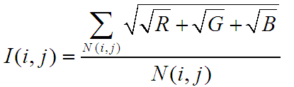
//計算每一塊區域的光照均值sqrt(sqrt(R)+sqrt(G)+sqrt(B))//光照均值是對稱矩陣,所以一次循環計算兩個光照值,(i,j),與(j,i)
for(inti=0;ifor(intj=i;jRectroi;//判斷image[i]與image[j]是否有重疊部分
if(overlapRoi(corners[i],corners[j],images[i].size(),images[j].size(),roi)){
subimg1=images[i](Rect(roi.tl()-corners[i],roi.br()-corners[i]));subimg2=images[j](Rect(roi.tl()-corners[j],roi.br()-corners[j]));
submask1=masks[i].first(Rect(roi.tl()-corners[i],roi.br()-corners[i]));
submask2=masks[j].first(Rect(roi.tl()-corners[j],roi.br()-corners[j]));intersect=(submask1==masks[i].second)&(submask2==masks[j].second);
N(i,j)=N(j,i)=max(1,countNonZero(intersect));
doubleIsum1=0,Isum2=0;
for(inty=0;yconstPoint3_*r1=subimg1.ptr>(y);constPoint3_*r2=subimg2.ptr>(y);
for(intx=0;xif(intersect(y,x)){
Isum1+=sqrt(static_cast(sqr(r1[x].x)+sqr(r1[x].y)+sqr(r1[x].z)));Isum2+=sqrt(static_cast(sqr(r2[x].x)+sqr(r2[x].y)+sqr(r2[x].z)));
}}
}I(i,j)=Isum1/N(i,j);
I(j,i)=Isum2/N(i,j);}
}}
//計算每一塊區域的光照均值sqrt(sqrt(R)+sqrt(G)+sqrt(B))
//光照均值是對稱矩陣,所以一次循環計算兩個光照值,(i,j),與(j,i)
for (int i = 0; i < num_images; ++i)
{
for (int j = i; j < num_images; ++j)
{
Rect roi;
//判斷image[i]與image[j]是否有重疊部分
if (overlapRoi(corners[i], corners[j], images[i].size(), images[j].size(), roi))
{
subimg1 = images[i](Rect(roi.tl() - corners[i], roi.br() - corners[i]));
subimg2 = images[j](Rect(roi.tl() - corners[j], roi.br() - corners[j]));
submask1 = masks[i].first(Rect(roi.tl() - corners[i], roi.br() - corners[i]));
submask2 = masks[j].first(Rect(roi.tl() - corners[j], roi.br() - corners[j]));
intersect = (submask1 == masks[i].second) & (submask2 == masks[j].second);
N(i, j) = N(j, i) = max(1, countNonZero(intersect));
double Isum1 = 0, Isum2 = 0;
for (int y = 0; y < roi.height; ++y)
{
const Point3_* r1 = subimg1.ptr >(y);
const Point3_* r2 = subimg2.ptr >(y);
for (int x = 0; x < roi.width; ++x)
{
if (intersect(y, x))
{
Isum1 += sqrt(static_cast(sqr(r1[x].x) + sqr(r1[x].y) + sqr(r1[x].z)));
Isum2 += sqrt(static_cast(sqr(r2[x].x) + sqr(r2[x].y) + sqr(r2[x].z)));
}
}
}
I(i, j) = Isum1 / N(i, j);
I(j, i) = Isum2 / N(i, j);
}
}
}
建立方程,求出每個光強的調整系數
view plaincopyprint?
Mat_A(num_images,num_images);A.setTo(0);Mat_b(num_images,1);b.setTo(0);//beta*N(i,j)
for(inti=0;ifor(intj=0;jb(i,0)+=beta*N(i,j);A(i,i)+=beta*N(i,j);
if(j==i)continue;A(i,i)+=2*alpha*I(i,j)*I(i,j)*N(i,j);
A(i,j)-=2*alpha*I(i,j)*I(j,i)*N(i,j);}
}
solve(A,b,gains_);//求方程的解A*gains=B
Mat_ A(num_images, num_images); A.setTo(0);
Mat_ b(num_images, 1); b.setTo(0);//beta*N(i,j)
for (int i = 0; i < num_images; ++i)
{
for (int j = 0; j < num_images; ++j)
{
b(i, 0) += beta * N(i, j);
A(i, i) += beta * N(i, j);
if (j == i) continue;
A(i, i) += 2 * alpha * I(i, j) * I(i, j) * N(i, j);
A(i, j) -= 2 * alpha * I(i, j) * I(j, i) * N(i, j);
}
}
solve(A, b, gains_);//求方程的解A*gains = B
gains_原理分析:
num_images :表示圖像分塊的個數,零num_images = n
N矩陣,大小n*n,N(i,j)表示第i幅圖像與第j幅圖像重合的像素點數,N(i,j)=N(j,i)
I矩陣,大小n*n,I(i,j)與I(j,i)表示第i,j塊區域重合部分的像素平均值,I(i,j)是重合區域中i快的平均亮度值,
參數alpha和beta,默認值是alpha=0.01,beta=100.
A矩陣,大小n*n,公式圖片不全
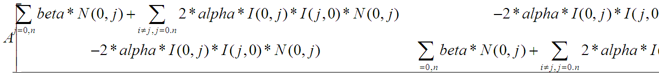
b矩陣,大小n*1,
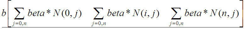
然後根據求解矩陣
gains_矩陣,大小1*n,A*gains = B
然後將gains_進行線性濾波
view plaincopyprint?
Mat_ker(1,3);ker(0,0)=0.25;ker(0,1)=0.5;ker(0,2)=0.25;
intbl_idx=0;
for(intimg_idx=0;img_idxSizebl_per_img=bl_per_imgs[img_idx];gain_maps_[img_idx].create(bl_per_img);
for(intby=0;byfor(intbx=0;bx(gains[bl_idx]);
//用分解的核函數對圖像做卷積。首先,圖像的每一行與一維的核kernelX做卷積;然後,運算結果的每一列與一維的核kernelY做卷積sepFilter2D(gain_maps_[img_idx],gain_maps_[img_idx],CV_32F,ker,ker);
sepFilter2D(gain_maps_[img_idx],gain_maps_[img_idx],CV_32F,ker,ker);}
Mat_ ker(1, 3);
ker(0,0) = 0.25; ker(0,1) = 0.5; ker(0,2) = 0.25;
int bl_idx = 0;
for (int img_idx = 0; img_idx < num_images; ++img_idx)
{
Size bl_per_img = bl_per_imgs[img_idx];
gain_maps_[img_idx].create(bl_per_img);
for (int by = 0; by < bl_per_img.height; ++by)
for (int bx = 0; bx < bl_per_img.width; ++bx, ++bl_idx)
gain_maps_[img_idx](by, bx) = static_cast(gains[bl_idx]);
//用分解的核函數對圖像做卷積。首先,圖像的每一行與一維的核kernelX做卷積;然後,運算結果的每一列與一維的核kernelY做卷積
sepFilter2D(gain_maps_[img_idx], gain_maps_[img_idx], CV_32F, ker, ker);
sepFilter2D(gain_maps_[img_idx], gain_maps_[img_idx], CV_32F, ker, ker);
}
然後構建一個gain_maps的三維矩陣,gain_main[圖像的個數][圖像分塊的行數][圖像分塊的列數],然後對沒一副圖像的gain進行濾波。
9.Seam Estimation
縫隙估計有6種方法,默認就是第三種方法,seam_find_type == "gc_color",該方法是利用最大流方法檢測。
view plaincopyprint?
if(seam_find_type=="no")seam_finder=newdetail::NoSeamFinder();//Stubseamestimatorwhichdoesnothing.
elseif(seam_find_type=="voronoi")seam_finder=newdetail::VoronoiSeamFinder();//Voronoidiagram-basedseamestimator.泰森多邊形縫隙估計
elseif(seam_find_type=="gc_color"){
#ifdefHAVE_OPENCV_GPUif(try_gpu&&gpu::getCudaEnabledDeviceCount()>0)
seam_finder=newdetail::GraphCutSeamFinderGpu(GraphCutSeamFinderBase::COST_COLOR);else
#endifseam_finder=newdetail::GraphCutSeamFinder(GraphCutSeamFinderBase::COST_COLOR);//Minimumgraphcut-basedseamestimator
}elseif(seam_find_type=="gc_colorgrad")
{#ifdefHAVE_OPENCV_GPU
if(try_gpu&&gpu::getCudaEnabledDeviceCount()>0)seam_finder=newdetail::GraphCutSeamFinderGpu(GraphCutSeamFinderBase::COST_COLOR_GRAD);
else#endif
seam_finder=newdetail::GraphCutSeamFinder(GraphCutSeamFinderBase::COST_COLOR_GRAD);}
elseif(seam_find_type=="dp_color")seam_finder=newdetail::DpSeamFinder(DpSeamFinder::COLOR);
elseif(seam_find_type=="dp_colorgrad")seam_finder=newdetail::DpSeamFinder(DpSeamFinder::COLOR_GRAD);
if(seam_finder.empty()){
cout<<"Can'tcreatethefollowingseamfinder'"<}
if (seam_find_type == "no")
seam_finder = new detail::NoSeamFinder();//Stub seam estimator which does nothing.
else if (seam_find_type == "voronoi")
seam_finder = new detail::VoronoiSeamFinder();//Voronoi diagram-based seam estimator. 泰森多邊形縫隙估計
else if (seam_find_type == "gc_color")
{
#ifdef HAVE_OPENCV_GPU
if (try_gpu && gpu::getCudaEnabledDeviceCount() > 0)
seam_finder = new detail::GraphCutSeamFinderGpu(GraphCutSeamFinderBase::COST_COLOR);
else
#endif
seam_finder = new detail::GraphCutSeamFinder(GraphCutSeamFinderBase::COST_COLOR);//Minimum graph cut-based seam estimator
}
else if (seam_find_type == "gc_colorgrad")
{
#ifdef HAVE_OPENCV_GPU
if (try_gpu && gpu::getCudaEnabledDeviceCount() > 0)
seam_finder = new detail::GraphCutSeamFinderGpu(GraphCutSeamFinderBase::COST_COLOR_GRAD);
else
#endif
seam_finder = new detail::GraphCutSeamFinder(GraphCutSeamFinderBase::COST_COLOR_GRAD);
}
else if (seam_find_type == "dp_color")
seam_finder = new detail::DpSeamFinder(DpSeamFinder::COLOR);
else if (seam_find_type == "dp_colorgrad")
seam_finder = new detail::DpSeamFinder(DpSeamFinder::COLOR_GRAD);
if (seam_finder.empty())
{
cout << "Can't create the following seam finder '" << seam_find_type << "'\n";
return 1;
}
程序解讀可參見:
http://blog.csdn.net/chlele0105/article/details/12624541
http://blog.csdn.net/zouxy09/article/details/8534954
http://blog.csdn.net/yangtrees/article/details/7930640
10.多波段融合
由於以前進行處理的圖片都是以work_scale(3.1節有介紹)進行縮放的,所以圖像的內參,corner(同一坐標後的頂點),mask(融合的掩碼)都需要重新計算。以及將之前計算的光照增強的gain也要計算進去。
view plaincopyprint?
//Readimageandresizeitifnecessaryfull_img=imread(img_names[img_idx]);
if(!is_compose_scale_set){
if(compose_megapix>0)compose_scale=min(1.0,sqrt(compose_megapix*1e6/full_img.size().area()));
is_compose_scale_set=true;
//Computerelativescales//compose_seam_aspect=compose_scale/seam_scale;
compose_work_aspect=compose_scale/work_scale;
//Updatewarpedimagescalewarped_image_scale*=static_cast(compose_work_aspect);
warper=warper_creator->create(warped_image_scale);
//Updatecornersandsizesfor(inti=0;i{//Updateintrinsics
cameras[i].focal*=compose_work_aspect;cameras[i].ppx*=compose_work_aspect;
cameras[i].ppy*=compose_work_aspect;
//UpdatecornerandsizeSizesz=full_img_sizes[i];
if(std::abs(compose_scale-1)>1e-1){
sz.width=cvRound(full_img_sizes[i].width*compose_scale);//取整sz.height=cvRound(full_img_sizes[i].height*compose_scale);
}
MatK;cameras[i].K().convertTo(K,CV_32F);
Rectroi=warper->warpRoi(sz,K,cameras[i].R);//ReturnsProjectedimageminimumboundingboxcorners[i]=roi.tl();//!thetop-leftcorner
sizes[i]=roi.size();//!sizeoftherealbuffer}
}if(abs(compose_scale-1)>1e-1)
resize(full_img,img,Size(),compose_scale,compose_scale);else
img=full_img;full_img.release();
Sizeimg_size=img.size();
MatK;cameras[img_idx].K().convertTo(K,CV_32F);
//Warpthecurrentimage
warper->warp(img,K,cameras[img_idx].R,INTER_LINEAR,BORDER_REFLECT,img_warped);//Warpthecurrentimagemask
mask.create(img_size,CV_8U);mask.setTo(Scalar::all(255));
warper->warp(mask,K,cameras[img_idx].R,INTER_NEAREST,BORDER_CONSTANT,mask_warped);//Compensateexposure
compensator->apply(img_idx,corners[img_idx],img_warped,mask_warped);//光照補償img_warped.convertTo(img_warped_s,CV_16S);
img_warped.release();img.release();
mask.release();
dilate(masks_warped[img_idx],dilated_mask,Mat());resize(dilated_mask,seam_mask,mask_warped.size());
mask_warped=seam_mask&mask_warped;
// Read image and resize it if necessary
full_img = imread(img_names[img_idx]);
if (!is_compose_scale_set)
{
if (compose_megapix > 0)
compose_scale = min(1.0, sqrt(compose_megapix * 1e6 / full_img.size().area()));
is_compose_scale_set = true;
// Compute relative scales
//compose_seam_aspect = compose_scale / seam_scale;
compose_work_aspect = compose_scale / work_scale;
// Update warped image scale
warped_image_scale *= static_cast(compose_work_aspect);
warper = warper_creator->create(warped_image_scale);
// Update corners and sizes
for (int i = 0; i < num_images; ++i)
{
// Update intrinsics
cameras[i].focal *= compose_work_aspect;
cameras[i].ppx *= compose_work_aspect;
cameras[i].ppy *= compose_work_aspect;
// Update corner and size
Size sz = full_img_sizes[i];
if (std::abs(compose_scale - 1) > 1e-1)
{
sz.width = cvRound(full_img_sizes[i].width * compose_scale);//取整
sz.height = cvRound(full_img_sizes[i].height * compose_scale);
}
Mat K;
cameras[i].K().convertTo(K, CV_32F);
Rect roi = warper->warpRoi(sz, K, cameras[i].R);//Returns Projected image minimum bounding box
corners[i] = roi.tl();//! the top-left corner
sizes[i] = roi.size();//! size of the real buffer
}
}
if (abs(compose_scale - 1) > 1e-1)
resize(full_img, img, Size(), compose_scale, compose_scale);
else
img = full_img;
full_img.release();
Size img_size = img.size();
Mat K;
cameras[img_idx].K().convertTo(K, CV_32F);
// Warp the current image
warper->warp(img, K, cameras[img_idx].R, INTER_LINEAR, BORDER_REFLECT, img_warped);
// Warp the current image mask
mask.create(img_size, CV_8U);
mask.setTo(Scalar::all(255));
warper->warp(mask, K, cameras[img_idx].R, INTER_NEAREST, BORDER_CONSTANT, mask_warped);
// Compensate exposure
compensator->apply(img_idx, corners[img_idx], img_warped, mask_warped);//光照補償
img_warped.convertTo(img_warped_s, CV_16S);
img_warped.release();
img.release();
mask.release();
dilate(masks_warped[img_idx], dilated_mask, Mat());
resize(dilated_mask, seam_mask, mask_warped.size());
mask_warped = seam_mask & mask_warped;
對圖像進行光照補償,就是將對應區域乘以gain:
view plaincopyprint?
//塊光照補償voidBlocksGainCompensator::apply(intindex,Point/*corner*/,Mat&image,constMat&/*mask*/)
{CV_Assert(image.type()==CV_8UC3);
Mat_gain_map;
if(gain_maps_[index].size()==image.size())gain_map=gain_maps_[index];
elseresize(gain_maps_[index],gain_map,image.size(),0,0,INTER_LINEAR);
for(inty=0;y{constfloat*gain_row=gain_map.ptr(y);
Point3_*row=image.ptr>(y);for(intx=0;x{row[x].x=saturate_cast(row[x].x*gain_row[x]);
row[x].y=saturate_cast(row[x].y*gain_row[x]);row[x].z=saturate_cast(row[x].z*gain_row[x]);
}}
}
//塊光照補償
void BlocksGainCompensator::apply(int index, Point /*corner*/, Mat &image, const Mat &/*mask*/)
{
CV_Assert(image.type() == CV_8UC3);
Mat_ gain_map;
if (gain_maps_[index].size() == image.size())
gain_map = gain_maps_[index];
else
resize(gain_maps_[index], gain_map, image.size(), 0, 0, INTER_LINEAR);
for (int y = 0; y < image.rows; ++y)
{
const float* gain_row = gain_map.ptr(y);
Point3_* row = image.ptr >(y);
for (int x = 0; x < image.cols; ++x)
{
row[x].x = saturate_cast(row[x].x * gain_row[x]);
row[x].y = saturate_cast(row[x].y * gain_row[x]);
row[x].z = saturate_cast(row[x].z * gain_row[x]);
}
}
}
進行多波段融合,首先初始化blend,確定blender的融合的方式,默認是多波段融合MULTI_BAND,以及根據corners頂點和圖像的大小確定最終全景圖的尺寸。
view plaincopyprint?
//初始化blenderif(blender.empty())
{blender=Blender::createDefault(blend_type,try_gpu);
Sizedst_sz=resultRoi(corners,sizes).size();//計算最後圖像的大小floatblend_width=sqrt(static_cast(dst_sz.area()))*blend_strength/100.f;
if(blend_width<1.f)blender=Blender::createDefault(Blender::NO,try_gpu);
elseif(blend_type==Blender::MULTI_BAND){
MultiBandBlender*mb=dynamic_cast(static_cast(blender));mb->setNumBands(static_cast(ceil(log(blend_width)/log(2.))-1.));
LOGLN("Multi-bandblender,numberofbands:"
elseif(blend_type==Blender::FEATHER){
FeatherBlender*fb=dynamic_cast(static_cast(blender));fb->setSharpness(1.f/blend_width);
LOGLN("Featherblender,sharpness:"
blender->prepare(corners,sizes);//根據corners頂點和圖像的大小確定最終全景圖的尺寸}
//初始化blender
if (blender.empty())
{
blender = Blender::createDefault(blend_type, try_gpu);
Size dst_sz = resultRoi(corners, sizes).size();//計算最後圖像的大小
float blend_width = sqrt(static_cast(dst_sz.area())) * blend_strength / 100.f;
if (blend_width < 1.f)
blender = Blender::createDefault(Blender::NO, try_gpu);
else if (blend_type == Blender::MULTI_BAND)
{
MultiBandBlender* mb = dynamic_cast(static_cast(blender));
mb->setNumBands(static_cast(ceil(log(blend_width)/log(2.)) - 1.));
LOGLN("Multi-band blender, number of bands: " << mb->numBands());
}
else if (blend_type == Blender::FEATHER)
{
FeatherBlender* fb = dynamic_cast(static_cast(blender));
fb->setSharpness(1.f/blend_width);
LOGLN("Feather blender, sharpness: " << fb->sharpness());
}
blender->prepare(corners, sizes);//根據corners頂點和圖像的大小確定最終全景圖的尺寸
}
然後對每幅圖圖形構建金字塔,層數可以由輸入的系數確定,默認是5層。
先對頂點以及圖像的寬和高做處理,使其能被2^num_bands除盡,這樣才能將進行向下采樣num_bands次,首先從源圖像pyrDown向下采樣,在由最底部的圖像pyrUp向上采樣,把對應層得上采樣和下采樣的相減,就得到了圖像的高頻分量,存儲到每一個金字塔中。然後根據mask,將每幅圖像的各層金字塔分別寫入最終的金字塔層src_pyr_laplace中。
最後將各層的金字塔疊加,就得到了最終完整的全景圖。
view plaincopyprint?
blender->feed(img_warped_s,mask_warped,corners[img_idx]);//將圖像寫入金字塔中
blender->feed(img_warped_s, mask_warped, corners[img_idx]);//將圖像寫入金字塔中
源碼:
view plaincopyprint?
voidMultiBandBlender::feed(constMat&img,constMat&mask,Pointtl){
CV_Assert(img.type()==CV_16SC3||img.type()==CV_8UC3);CV_Assert(mask.type()==CV_8U);
//Keepsourceimageinmemorywithsmallborder
intgap=3*(1
min(dst_roi_.br().y,tl.y+img.rows+gap));
//Ensurecoordinatesoftop-left,bottom-rightcornersaredividedby(1
//imageisborderedtohavesizeequaltothefinalimagesize,butthisistoomemoryhungryapproach.//將頂點調整成能被2^num_bank次方除盡的值
tl_new.x=dst_roi_.x+(((tl_new.x-dst_roi_.x)>>num_bands_)<>num_bands_)
width+=((1
intdy=max(br_new.y-dst_roi_.br().y,0);intdx=max(br_new.x-dst_roi_.br().x,0);
tl_new.x-=dx;br_new.x-=dx;tl_new.y-=dy;br_new.y-=dy;
inttop=tl.y-tl_new.y;
intleft=tl.x-tl_new.x;intbottom=br_new.y-tl.y-img.rows;
intright=br_new.x-tl.x-img.cols;
//CreatethesourceimageLaplacianpyramidMatimg_with_border;
copyMakeBorder(img,img_with_border,top,bottom,left,right,BORDER_REFLECT);//給圖像設置一個邊界,BORDER_REFLECT邊界顏色任意
vectorsrc_pyr_laplace;if(can_use_gpu_&&img_with_border.depth()==CV_16S)
createLaplacePyrGpu(img_with_border,num_bands_,src_pyr_laplace);else
createLaplacePyr(img_with_border,num_bands_,src_pyr_laplace);//創建高斯金字塔,每一層保存的全是高頻信息
//CreatetheweightmapGaussianpyramidMatweight_map;
vectorweight_pyr_gauss(num_bands_+1);
if(weight_type_==CV_32F){
mask.convertTo(weight_map,CV_32F,1./255.);//將mask的0,255歸一化成0,1}
else//weight_type_==CV_16S{
mask.convertTo(weight_map,CV_16S);add(weight_map,1,weight_map,mask!=0);
}
copyMakeBorder(weight_map,weight_pyr_gauss[0],top,bottom,left,right,BORDER_CONSTANT);
for(inti=0;iinty_tl=tl_new.y-dst_roi_.y;
inty_br=br_new.y-dst_roi_.y;intx_tl=tl_new.x-dst_roi_.x;
intx_br=br_new.x-dst_roi_.x;
//AddweightedlayerofthesourceimagetothefinalLaplacianpyramidlayerif(weight_type_==CV_32F)
{for(inti=0;i<=num_bands_;++i)
{for(inty=y_tl;y{inty_=y-y_tl;
constPoint3_*src_row=src_pyr_laplace[i].ptr>(y_);Point3_*dst_row=dst_pyr_laplace_[i].ptr>(y);
constfloat*weight_row=weight_pyr_gauss[i].ptr(y_);float*dst_weight_row=dst_band_weights_[i].ptr(y);
for(intx=x_tl;x{intx_=x-x_tl;
dst_row[x].x+=static_cast(src_row[x_].x*weight_row[x_]);dst_row[x].y+=static_cast(src_row[x_].y*weight_row[x_]);
dst_row[x].z+=static_cast(src_row[x_].z*weight_row[x_]);dst_weight_row[x]+=weight_row[x_];
}}
x_tl/=2;y_tl/=2;x_br/=2;y_br/=2;
}}
else//weight_type_==CV_16S{
for(inti=0;i<=num_bands_;++i){
for(inty=y_tl;yinty_=y-y_tl;constPoint3_*src_row=src_pyr_laplace[i].ptr>(y_);
Point3_*dst_row=dst_pyr_laplace_[i].ptr>(y);constshort*weight_row=weight_pyr_gauss[i].ptr(y_);
short*dst_weight_row=dst_band_weights_[i].ptr(y);
for(intx=x_tl;xintx_=x-x_tl;dst_row[x].x+=short((src_row[x_].x*weight_row[x_])>>8);
dst_row[x].y+=short((src_row[x_].y*weight_row[x_])>>8);dst_row[x].z+=short((src_row[x_].z*weight_row[x_])>>8);
dst_weight_row[x]+=weight_row[x_];}
}x_tl/=2;y_tl/=2;
x_br/=2;y_br/=2;}
}}
void MultiBandBlender::feed(const Mat &img, const Mat &mask, Point tl)
{
CV_Assert(img.type() == CV_16SC3 || img.type() == CV_8UC3);
CV_Assert(mask.type() == CV_8U);
// Keep source image in memory with small border
int gap = 3 * (1 << num_bands_);
Point tl_new(max(dst_roi_.x, tl.x - gap),
max(dst_roi_.y, tl.y - gap));
Point br_new(min(dst_roi_.br().x, tl.x + img.cols + gap),
min(dst_roi_.br().y, tl.y + img.rows + gap));
// Ensure coordinates of top-left, bottom-right corners are divided by (1 << num_bands_).
// After that scale between layers is exactly 2.
//
// We do it to avoid interpolation problems when keeping sub-images only. There is no such problem when
// image is bordered to have size equal to the final image size, but this is too memory hungry approach.
//將頂點調整成能被2^num_bank次方除盡的值
tl_new.x = dst_roi_.x + (((tl_new.x - dst_roi_.x) >> num_bands_) << num_bands_);
tl_new.y = dst_roi_.y + (((tl_new.y - dst_roi_.y) >> num_bands_) << num_bands_);
int width = br_new.x - tl_new.x;
int height = br_new.y - tl_new.y;
width += ((1 << num_bands_) - width % (1 << num_bands_)) % (1 << num_bands_);
height += ((1 << num_bands_) - height % (1 << num_bands_)) % (1 << num_bands_);
br_new.x = tl_new.x + width;
br_new.y = tl_new.y + height;
int dy = max(br_new.y - dst_roi_.br().y, 0);
int dx = max(br_new.x - dst_roi_.br().x, 0);
tl_new.x -= dx; br_new.x -= dx;
tl_new.y -= dy; br_new.y -= dy;
int top = tl.y - tl_new.y;
int left = tl.x - tl_new.x;
int bottom = br_new.y - tl.y - img.rows;
int right = br_new.x - tl.x - img.cols;
// Create the source image Laplacian pyramid
Mat img_with_border;
copyMakeBorder(img, img_with_border, top, bottom, left, right,
BORDER_REFLECT);//給圖像設置一個邊界,BORDER_REFLECT邊界顏色任意
vector src_pyr_laplace;
if (can_use_gpu_ && img_with_border.depth() == CV_16S)
createLaplacePyrGpu(img_with_border, num_bands_, src_pyr_laplace);
else
createLaplacePyr(img_with_border, num_bands_, src_pyr_laplace);//創建高斯金字塔,每一層保存的全是高頻信息
// Create the weight map Gaussian pyramid
Mat weight_map;
vector weight_pyr_gauss(num_bands_ + 1);
if(weight_type_ == CV_32F)
{
mask.convertTo(weight_map, CV_32F, 1./255.);//將mask的0,255歸一化成0,1
}
else// weight_type_ == CV_16S
{
mask.convertTo(weight_map, CV_16S);
add(weight_map, 1, weight_map, mask != 0);
}
copyMakeBorder(weight_map, weight_pyr_gauss[0], top, bottom, left, right, BORDER_CONSTANT);
for (int i = 0; i < num_bands_; ++i)
pyrDown(weight_pyr_gauss[i], weight_pyr_gauss[i + 1]);
int y_tl = tl_new.y - dst_roi_.y;
int y_br = br_new.y - dst_roi_.y;
int x_tl = tl_new.x - dst_roi_.x;
int x_br = br_new.x - dst_roi_.x;
// Add weighted layer of the source image to the final Laplacian pyramid layer
if(weight_type_ == CV_32F)
{
for (int i = 0; i <= num_bands_; ++i)
{
for (int y = y_tl; y < y_br; ++y)
{
int y_ = y - y_tl;
const Point3_* src_row = src_pyr_laplace[i].ptr >(y_);
Point3_* dst_row = dst_pyr_laplace_[i].ptr >(y);
const float* weight_row = weight_pyr_gauss[i].ptr(y_);
float* dst_weight_row = dst_band_weights_[i].ptr(y);
for (int x = x_tl; x < x_br; ++x)
{
int x_ = x - x_tl;
dst_row[x].x += static_cast(src_row[x_].x * weight_row[x_]);
dst_row[x].y += static_cast(src_row[x_].y * weight_row[x_]);
dst_row[x].z += static_cast(src_row[x_].z * weight_row[x_]);
dst_weight_row[x] += weight_row[x_];
}
}
x_tl /= 2; y_tl /= 2;
x_br /= 2; y_br /= 2;
}
}
else// weight_type_ == CV_16S
{
for (int i = 0; i <= num_bands_; ++i)
{
for (int y = y_tl; y < y_br; ++y)
{
int y_ = y - y_tl;
const Point3_* src_row = src_pyr_laplace[i].ptr >(y_);
Point3_* dst_row = dst_pyr_laplace_[i].ptr >(y);
const short* weight_row = weight_pyr_gauss[i].ptr(y_);
short* dst_weight_row = dst_band_weights_[i].ptr(y);
for (int x = x_tl; x < x_br; ++x)
{
int x_ = x - x_tl;
dst_row[x].x += short((src_row[x_].x * weight_row[x_]) >> 8);
dst_row[x].y += short((src_row[x_].y * weight_row[x_]) >> 8);
dst_row[x].z += short((src_row[x_].z * weight_row[x_]) >> 8);
dst_weight_row[x] += weight_row[x_];
}
}
x_tl /= 2; y_tl /= 2;
x_br /= 2; y_br /= 2;
}
}
}
其中,金字塔構建的源碼:
view plaincopyprint?
voidcreateLaplacePyr(constMat&img,intnum_levels,vector&pyr){
#ifdefHAVE_TEGRA_OPTIMIZATIONif(tegra::createLaplacePyr(img,num_levels,pyr))
return;#endif
pyr.resize(num_levels+1);
if(img.depth()==CV_8U)
{if(num_levels==0)
{img.convertTo(pyr[0],CV_16S);
return;}
MatdownNext;
Matcurrent=img;pyrDown(img,downNext);
for(inti=1;i{Matlvl_up;
Matlvl_down;
pyrDown(downNext,lvl_down);pyrUp(downNext,lvl_up,current.size());
subtract(current,lvl_up,pyr[i-1],noArray(),CV_16S);
current=downNext;downNext=lvl_down;
}
{Matlvl_up;
pyrUp(downNext,lvl_up,current.size());subtract(current,lvl_up,pyr[num_levels-1],noArray(),CV_16S);
downNext.convertTo(pyr[num_levels],CV_16S);
}}
else{
pyr[0]=img;//構建高斯金字塔
for(inti=0;iMattmp;for(inti=0;i{pyrUp(pyr[i+1],tmp,pyr[i].size());//插值(偶數行,偶數列賦值為0),然後高斯濾波,核是5*5。
subtract(pyr[i],tmp,pyr[i]);//pyr[i]=pyr[i]-tmp,得到的全是高頻信息}
}}
void createLaplacePyr(const Mat &img, int num_levels, vector &pyr)
{
#ifdef HAVE_TEGRA_OPTIMIZATION
if(tegra::createLaplacePyr(img, num_levels, pyr))
return;
#endif
pyr.resize(num_levels + 1);
if(img.depth() == CV_8U)
{
if(num_levels == 0)
{
img.convertTo(pyr[0], CV_16S);
return;
}
Mat downNext;
Mat current = img;
pyrDown(img, downNext);
for(int i = 1; i < num_levels; ++i)
{
Mat lvl_up;
Mat lvl_down;
pyrDown(downNext, lvl_down);
pyrUp(downNext, lvl_up, current.size());
subtract(current, lvl_up, pyr[i-1], noArray(), CV_16S);
current = downNext;
downNext = lvl_down;
}
{
Mat lvl_up;
pyrUp(downNext, lvl_up, current.size());
subtract(current, lvl_up, pyr[num_levels-1], noArray(), CV_16S);
downNext.convertTo(pyr[num_levels], CV_16S);
}
}
else
{
pyr[0] = img;
//構建高斯金字塔
for (int i = 0; i < num_levels; ++i)
pyrDown(pyr[i], pyr[i + 1]);//先高斯濾波,在亞采樣,得到比pyr【i】縮小一半的圖像
Mat tmp;
for (int i = 0; i < num_levels; ++i)
{
pyrUp(pyr[i + 1], tmp, pyr[i].size());//插值(偶數行,偶數列賦值為0),然後高斯濾波,核是5*5。
subtract(pyr[i], tmp, pyr[i]);//pyr[i] = pyr[i]-tmp,得到的全是高頻信息
}
}
}
最終把所有層得金字塔疊加的程序:
view plaincopyprint?
Matresult,result_mask;blender->blend(result,result_mask);//將多層金字塔圖形疊加
Mat result, result_mask;
blender->blend(result, result_mask);//將多層金字塔圖形疊加
源碼:
view plaincopyprint?
voidMultiBandBlender::blend(Mat&dst,Mat&dst_mask){
for(inti=0;i<=num_bands_;++i)normalizeUsingWeightMap(dst_band_weights_[i],dst_pyr_laplace_[i]);
if(can_use_gpu_)
restoreImageFromLaplacePyrGpu(dst_pyr_laplace_);else
restoreImageFromLaplacePyr(dst_pyr_laplace_);
dst_=dst_pyr_laplace_[0];dst_=dst_(Range(0,dst_roi_final_.height),Range(0,dst_roi_final_.width));
dst_mask_=dst_band_weights_[0]>WEIGHT_EPS;dst_mask_=dst_mask_(Range(0,dst_roi_final_.height),Range(0,dst_roi_final_.width));
dst_pyr_laplace_.clear();dst_band_weights_.clear();
Blender::blend(dst,dst_mask);
}
void MultiBandBlender::blend(Mat &dst, Mat &dst_mask)
{
for (int i = 0; i <= num_bands_; ++i)
normalizeUsingWeightMap(dst_band_weights_[i], dst_pyr_laplace_[i]);
if (can_use_gpu_)
restoreImageFromLaplacePyrGpu(dst_pyr_laplace_);
else
restoreImageFromLaplacePyr(dst_pyr_laplace_);
dst_ = dst_pyr_laplace_[0];
dst_ = dst_(Range(0, dst_roi_final_.height), Range(0, dst_roi_final_.width));
dst_mask_ = dst_band_weights_[0] > WEIGHT_EPS;
dst_mask_ = dst_mask_(Range(0, dst_roi_final_.height), Range(0, dst_roi_final_.width));
dst_pyr_laplace_.clear();
dst_band_weights_.clear();
Blender::blend(dst, dst_mask);
}
 Android繪圖那些事兒(上)
(一)概述雖然,已經學過了Android繪圖的內容,但是總是覺得很模糊,今天就好好梳理下思路吧!純粹就是一個讀書筆記,整理下自己以前不知道的內容,好了開始:(本節主要介紹
 android性能優化之布局優化
1、抽象布局標簽(1) 標簽include標簽常用於將布局中的公共部分提取出來供其他layout共用,以實現布局模塊化,這在布局編寫方便提供了大大的便利。下面以在一個布局
 Android開發自學筆記(五):使用代碼控制界面
酷酷的外表已經具備了,那就開始讓我們真正把它的功能給實現起來吧,外強中干,花拳繡腿可不行哦,我們需要真正的本領,需要一顆自強不息的心哦,常常想想自己的夢想什麼,這樣才不會
 Android library上傳到jcenter
Android library上傳到jcenter如何把我們開發好的Android library上傳到中央倉庫,供其他開發者方便使用,一行代碼來進行依賴,而不必下載源碼