編輯:關於Android編程
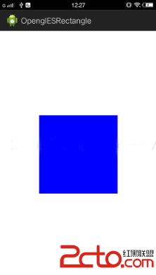
 因為加入了正交投影比起原先繪制矩形那一節的代碼有些變動,發生變動的文件有 MyRender.java , Square.java ,simple_vertex_shader.glsl ,此時這三個文件代碼如下:
package com.cumt.shape;

import java.nio.ByteBuffer;
import java.nio.ByteOrder;
import java.nio.FloatBuffer;
import com.cumt.openglesrectangle.R;
import com.cumt.utils.ShaderHelper;
import com.cumt.utils.TextResourceReader;
import android.content.Context;
import android.opengl.GLES20;
import android.opengl.Matrix;

public class Square {

    private Context context;

    //float類型的字節數
    private static final int BYTES_PER_FLOAT = 4;
    // 數組中每個頂點的坐標數
    static final int COORDS_PER_VERTEX = 2;

    /*------------------第一步: 修改頂點數據-------------------------*/
    //矩形頂點坐標
    static float squareCoords[] = { //以三角形扇的形式繪制
    	-0.5f,  0.5f ,   // top left
        0.5f,  0.5f  , // top right
        0.5f, -0.5f  , // bottom right
       -0.5f, -0.5f  };  // bottom left

    private FloatBuffer vertexBuffer;

    //------------第一個是頂點著色器的變量名,第二個是片段著色器的變量名
    private static final String A_POSITION = "a_Position";
    private static final String U_COLOR = "u_Color";
    private static final String U_MATRIX = "u_Matrix";
    //------------獲得program的ID的含義類似的
    private int uColorLocation;
    private int aPositionLocation;
    private int uMatrixLocation;
    private int program;//保存program的id

    /*------------------第二步: 修改頂點個數-------------------------*/
    private static final int POSITION_COMPONENT_COUNT = 4;

    float[] projectionMatrix = new float[16];//變換矩陣

    public Square(Context context) {
        this.context = context;
        vertexBuffer = ByteBuffer
                .allocateDirect(squareCoords.length * BYTES_PER_FLOAT)
                .order(ByteOrder.nativeOrder())
                .asFloatBuffer();
        // 把坐標們加入FloatBuffer中
        vertexBuffer.put(squareCoords);
        // 設置buffer,從第一個坐標開始讀
        vertexBuffer.position(0);

        getProgram();

        uColorLocation = GLES20.glGetUniformLocation(program, U_COLOR);
        aPositionLocation = GLES20.glGetAttribLocation(program, A_POSITION);
        uMatrixLocation = GLES20.glGetUniformLocation(program, U_MATRIX);

        GLES20.glVertexAttribPointer(aPositionLocation, COORDS_PER_VERTEX,
                GLES20.GL_FLOAT, false, 0, vertexBuffer);
        GLES20.glEnableVertexAttribArray(aPositionLocation);
    }

    //獲取program
    private void getProgram(){
        //獲取頂點著色器文本
        String vertexShaderSource = TextResourceReader
                .readTextFileFromResource(context, R.raw.simple_vertex_shader);
        //獲取片段著色器文本
        String fragmentShaderSource = TextResourceReader
                .readTextFileFromResource(context, R.raw.simple_fragment_shader);
        //獲取program的id
        program = ShaderHelper.buildProgram(vertexShaderSource, fragmentShaderSource);
        GLES20.glUseProgram(program);
    }

    //設置正交投影矩陣
    public void projectionMatrix(int width,int height){
        final float aspectRatio = width > height ?
                (float) width / (float) height :
                (float) height / (float) width;
        if(width > height){
            Matrix.orthoM(projectionMatrix, 0, -aspectRatio, aspectRatio, -1f, 1f, -1f, 1f);
        }else{
            Matrix.orthoM(projectionMatrix, 0, -1f, 1f, -aspectRatio, aspectRatio, -1f, 1f);
        }
    }

    //以GL_LINE_LOOP方式繪制
    public void draw(){
    	GLES20.glUniformMatrix4fv(uMatrixLocation, 1, false, projectionMatrix, 0);
        GLES20.glUniform4f(uColorLocation, 0.0f, 0.0f, 1.0f, 1.0f);
        /*------------------第三步: 修改繪制方式-------------------------*/
        GLES20.glDrawArrays(GLES20.GL_TRIANGLE_FAN, 0, POSITION_COMPONENT_COUNT);
    }
}
package com.cumt.render;
import javax.microedition.khronos.egl.EGLConfig;
import javax.microedition.khronos.opengles.GL10;

import com.cumt.shape.Square;
import android.content.Context;
import android.opengl.GLSurfaceView.Renderer;
import android.util.Log;
import static android.opengl.GLES20.glClear;
import static android.opengl.GLES20.glClearColor;
import static android.opengl.GLES20.glViewport;
import static android.opengl.GLES20.GL_COLOR_BUFFER_BIT;

public class MyRender implements Renderer {

    private Context context;

    public MyRender(Context context){
        this.context = context;
    }

    //定義矩形對象
    Square square;

    public void onSurfaceCreated(GL10 gl, EGLConfig config) {
        Log.w("MyRender","onSurfaceCreated");
        // TODO Auto-generated method stub
        //First:設置清空屏幕用的顏色,前三個參數對應紅綠藍,最後一個對應alpha
        glClearColor(1.0f, 1.0f, 1.0f, 0.0f);
        square = new Square(context);
    }

    public void onSurfaceChanged(GL10 gl, int width, int height) {
        Log.w("MyRender","onSurfaceChanged");
        // TODO Auto-generated method stub
        //Second:設置視口尺寸,即告訴opengl可以用來渲染的surface大小
        glViewport(0,0,width,height);
        square.projectionMatrix(width, height);
    }

    public void onDrawFrame(GL10 gl) {
        Log.w("MyRender","onDrawFrame");
        // TODO Auto-generated method stub
        //Third:清空屏幕,擦除屏幕上所有的顏色,並用之前glClearColor定義的顏色填充整個屏幕
        glClear(GL_COLOR_BUFFER_BIT);
        square.draw();
    }
}
//simple_vertex_shader.glsl
uniform mat4 u_Matrix;
attribute vec4 a_Position;

void main()
{
    gl_Position = u_Matrix * a_Position;
}

package com.cumt.utils;

import android.content.Context;
import android.graphics.Bitmap;
import android.graphics.BitmapFactory;
import android.opengl.GLES20;
import android.opengl.GLUtils;
import android.util.Log;

public class TextureHelper {

	public static final String TAG = "TextureHelper";

	public static int loadTexture(Context context,int resourceId){
		/*
		 * 第一步 : 創建紋理對象
		 */
		final int[] textureObjectId = new int[1];//用於存儲返回的紋理對象ID
		GLES20.glGenTextures(1,textureObjectId, 0);
		if(textureObjectId[0] == 0){//若返回為0,,則創建失敗
			if(LoggerConfig.ON){
				Log.w(TAG,"Could not generate a new Opengl texture object");
			}
			return 0;
		}
		/*
		 * 第二步: 加載位圖數據並與紋理綁定
		 */
		final BitmapFactory.Options options = new BitmapFactory.Options();
		options.inScaled = false;//Opengl需要非壓縮形式的原始數據
		final Bitmap bitmap = BitmapFactory.decodeResource(context.getResources(),resourceId, options);
		if(bitmap == null){
			if(LoggerConfig.ON){
				Log.w(TAG,"ResourceId:"+resourceId+"could not be decoded");
			}
			GLES20.glDeleteTextures(1, textureObjectId, 0);
			return 0;
		}
		GLES20.glBindTexture(GLES20.GL_TEXTURE_2D,textureObjectId[0]);//通過紋理ID進行綁定
		/*
		 * 第三步: 設置紋理過濾
		 */
		//設置縮小時為三線性過濾
		GLES20.glTexParameteri(GLES20.GL_TEXTURE_2D, GLES20.GL_TEXTURE_MIN_FILTER,GLES20.GL_LINEAR_MIPMAP_LINEAR);
		//設置放大時為雙線性過濾
		GLES20.glTexParameteri(GLES20.GL_TEXTURE_2D, GLES20.GL_TEXTURE_MAG_FILTER, GLES20.GL_LINEAR);
		/*
		 * 第四步: 加載紋理到Opengl並返回ID
		 */
		GLUtils.texImage2D(GLES20.GL_TEXTURE_2D, 0, bitmap, 0);
		bitmap.recycle();
		GLES20.glGenerateMipmap(GLES20.GL_TEXTURE_2D);
		return textureObjectId[0];
	}
}
//texture_vertex_shader.glsl
uniform mat4 u_Matrix;
attribute vec4 a_Position;
attribute vec2 a_TextureCoordinates;

varying vec2 v_TextureCoordinates;

void main()
{
    v_TextureCoordinates = a_TextureCoordinates;
    gl_Position = u_Matrix * a_Position;
}
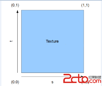
其中a_TextureCoordinates 用於接收紋理的坐標數據,v_TextureCoordinates用於將紋理數據傳遞給片段著色器,因為紋理有兩個分量 S與 T 所以使用vec2類型。
片段著色器如下:
//texture_fragment_shader.glsl
precision mediump float;
uniform sampler2D u_TextureUnit;
varying vec2 v_TextureCoordinates;

void main()
{
    gl_FragColor = texture2D(u_TextureUnit, v_TextureCoordinates);
}
//矩形頂點坐標  與 紋理坐標
    static float squareCoords[] = { //以三角形扇的形式繪制
    	//x     y       s   t
    	-0.5f,  0.5f ,  0 , 0 , // top left
        0.5f,  0.5f  ,  1 , 0 ,// top right
        0.5f, -0.5f  ,  1 , 1 ,// bottom right
       -0.5f, -0.5f  ,  0 , 1};  // bottom left
我們繪制的矩形的左上角對應著紋理的 (0,0 ) 大家注意這個映射關系,也就是我們拿出一張圖其左上角的紋理坐標為 (0,0)而不是 (0,1)。
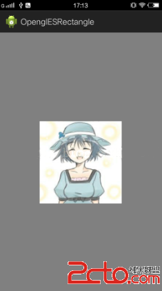
前面我們已經完成了紋理工具類,下面只需要使用它,然互將數據傳入著色器。此時Square類代碼如下 (Square.java):
package com.cumt.shape;

import static android.opengl.GLES20.GL_TEXTURE0;
import static android.opengl.GLES20.GL_TEXTURE_2D;
import static android.opengl.GLES20.glActiveTexture;
import static android.opengl.GLES20.glBindTexture;
import static android.opengl.GLES20.glUniform1i;
import java.nio.ByteBuffer;
import java.nio.ByteOrder;
import java.nio.FloatBuffer;
import com.cumt.openglesrectangle.R;
import com.cumt.utils.ShaderHelper;
import com.cumt.utils.TextResourceReader;
import com.cumt.utils.TextureHelper;
import android.content.Context;
import android.opengl.GLES20;
import android.opengl.Matrix;

public class Square {

    private Context context;

    //float類型的字節數
    private static final int BYTES_PER_FLOAT = 4;
    // 數組中每個頂點的坐標數
    static final int COORDS_PER_VERTEX = 2;

    /*------------------修改頂點數據 ,加入頂點對應的紋理坐標-------------------------*/
    //矩形頂點坐標  與 紋理坐標
    static float squareCoords[] = { //以三角形扇的形式繪制
    	//x     y       s   t
    	-0.5f,  0.5f ,  0 , 0 , // top left
        0.5f,  0.5f  ,  1 , 0 ,// top right
        0.5f, -0.5f  ,  1 , 1 ,// bottom right
       -0.5f, -0.5f  ,  0 , 1};  // bottom left

    private FloatBuffer vertexBuffer;
    private static final int VERTEX_COUNTS = 4;//頂點坐標數
    private static final int POSITION_COMPONENT_COUNT = 2;  //一個頂點坐標含有的元素個數
    private static final int TEXTURE_COORDIANTES_COMPONENT_COUNT = 2; //一個紋理坐標含有的元素個數
    //因為我們的頂點數據和紋理坐標數據放在了一起 ,所以在使用glVertexAttribPointer等函數時,其中的stride參數就需要傳入了,
    //用於高速著色器應該如何讀取坐標值 ,比如這裡我們的著色器讀取坐標時,設置從位置 0開始讀,讀取x , y後就會跳過 s t 接著讀取 x y
    //這就是通過傳入stride參數實現的
	private static final int STRIDE = (POSITION_COMPONENT_COUNT + TEXTURE_COORDIANTES_COMPONENT_COUNT)
			* BYTES_PER_FLOAT;
    //------------第一個是頂點著色器的變量名,第二個是片段著色器的變量名
    private static final String A_POSITION = "a_Position";
    private static final String U_MATRIX = "u_Matrix";
    private static final String A_TEXTURE_COORDINATES = "a_TextureCoordinates";//紋理
	private static final String U_TEXTURE_UNIT = "u_TextureUnit";//紋理

    private int aPositionLocation;
    private int uMatrixLocation;
    private int uTextureUnitLocation;
    private int aTextureCoordinates;
    private int program;//保存program的id
    private int texture;

    float[] projectionMatrix = new float[16];//變換矩陣

    public Square(Context context) {
        this.context = context;
        vertexBuffer = ByteBuffer
                .allocateDirect(squareCoords.length * BYTES_PER_FLOAT)
                .order(ByteOrder.nativeOrder())
                .asFloatBuffer();
        // 把坐標們加入FloatBuffer中
        vertexBuffer.put(squareCoords);
        // 設置buffer,從第一個坐標開始讀
        vertexBuffer.position(0);

        getProgram();

        aPositionLocation = GLES20.glGetAttribLocation(program, A_POSITION);
        uMatrixLocation = GLES20.glGetUniformLocation(program, U_MATRIX);
        aTextureCoordinates = GLES20.glGetAttribLocation(program, A_TEXTURE_COORDINATES);
		uTextureUnitLocation = GLES20.glGetAttribLocation(program, U_TEXTURE_UNIT);
		texture = TextureHelper.loadTexture(context, R.drawable.umei);
		// Set the active texture unit to texture unit 0.
        glActiveTexture(GL_TEXTURE0);
        // Bind the texture to this unit.
        glBindTexture(GL_TEXTURE_2D, texture);
        // Tell the texture uniform sampler to use this texture in the shader by
        // telling it to read from texture unit 0.
        glUniform1i(uTextureUnitLocation, 0);
        //傳入頂點坐標和紋理坐標
        GLES20.glVertexAttribPointer(aPositionLocation, POSITION_COMPONENT_COUNT,
				GLES20.GL_FLOAT, false, STRIDE, vertexBuffer);
		GLES20.glEnableVertexAttribArray(aPositionLocation);
		//設置從第二個元素開始讀取,因為從第二個元素開始才是紋理坐標
		vertexBuffer.position(POSITION_COMPONENT_COUNT);
		GLES20.glVertexAttribPointer(aTextureCoordinates, TEXTURE_COORDIANTES_COMPONENT_COUNT,
				GLES20.GL_FLOAT, false, STRIDE, vertexBuffer);
		GLES20.glEnableVertexAttribArray(aTextureCoordinates);
    }

    //獲取program
    private void getProgram(){
        //獲取頂點著色器文本
        String vertexShaderSource = TextResourceReader
                .readTextFileFromResource(context, R.raw.texture_vertex_shader);
        //獲取片段著色器文本
        String fragmentShaderSource = TextResourceReader
                .readTextFileFromResource(context, R.raw.texture_fragment_shader);
        //獲取program的id
        program = ShaderHelper.buildProgram(vertexShaderSource, fragmentShaderSource);
        GLES20.glUseProgram(program);
    }

    //設置正交投影矩陣
    public void projectionMatrix(int width,int height){
        final float aspectRatio = width > height ?
                (float) width / (float) height :
                (float) height / (float) width;
        if(width > height){
            Matrix.orthoM(projectionMatrix, 0, -aspectRatio, aspectRatio, -1f, 1f, -1f, 1f);
        }else{
            Matrix.orthoM(projectionMatrix, 0, -1f, 1f, -aspectRatio, aspectRatio, -1f, 1f);
        }
    }

    //以GL_LINE_LOOP方式繪制
    public void draw(){
    	GLES20.glUniformMatrix4fv(uMatrixLocation, 1, false, projectionMatrix, 0);
        GLES20.glDrawArrays(GLES20.GL_TRIANGLE_FAN, 0, VERTEX_COUNTS);
    }
}
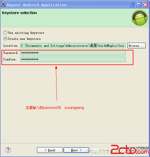 我的Android進階之旅------)Android中制作和查看自定義的Debug版本Android簽名證書
Android應用開發接入各種SDK時會發現,有很多SDK是需要靠package name和的證書指紋SHA1碼來識別的,如百度地圖SDK。這樣如果使用默認自動生成的de
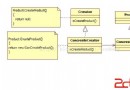 ANDROID 中設計模式的采用--創建型模式
所謂模式就是在某一情景下解決某個問題的固定解決方案。 所有的創建型模式都是用作對象的創建或實例化的解
 Android仿京東首頁輪播文字效果
京東客戶端的輪播文字效果:本次要實現的只是後面滾動的文字(前面的用ImageView或者TextView實現即可),看一下實現的效果實現思路上圖只是一個大概的思路,要實現
 Android 極速開發框架 dhroid
當我們編寫Android程序時候會出現大量重復工作,dhroid框架就很好解決這個問題。 dhroid 是基於android 平台, 極速開發框架,其核心設計目標是開發迅